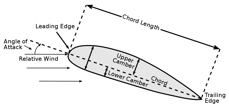

Aircraft affect the angle of attackĪngle at which the wing is attached to the aircraft fuselage. Is the angle between the chord line and the relative wind. Is the velocity of the airplane relative to the air mass through which it's flying. Parallel and in the opposite direction to the flight path Changing the shape of the wing changes the chord line Is the imaginary line from the leading edge to the trailing edge of an airfoil. Contains a leading edge, a trailing edge and a chord line. Structure or body which produce useful reaction to air movement. Name the parts at the Fore section of the plane

The wing is divided into 2 parts the half closest to the fuselage is the FLAPS and the section towards the end of the wing is the Aileron Vertical stabilizer, horizontal stabilizer, rudder, trim tabs, elevator Is an engine driven fixed wing aircraft heavier than air that is supported in flight by the dynamic reaction of air against it's wings Categories of aircraft are airplane, rotorcraft, lighter than air, power lift and glider

Is a device that is used or intended to be used for flight. It is possible to attach comments to the definition of the object these comments have no effect on its definition.Click here to study/print these flashcards.Ĭreate your own flash cards! Sign up here. Table entries consist of a sequence of curvilinear or axial coordinates and non-dimensional flap locations, d. For instance, for a 15% trailing edge flap, d = 0.70. The non-dimensional flap location, defined as the distance the flap hinge is aft the mid-chord normalized by the semi-chord length, d = 2d/c, is given in a table. The flap hinge location, denoted d, is shown in fig. However, if the airloads are computed internally, AirloadsScheme = 2D_AIRFOIL, the locations of the airstations in the wing and flap must be matched, AstLocation = MATCHED and the location of the flap hinge must be defined here. If an external code is used to compute airloads, the airstation locations on the wing and flap are arbitrary. It is possible to define a flap associated with an airstation. If no airtables are defined, the default coefficients defined in the section air property definition are used. Table entries consist of a sequence of curvilinear or axial coordinates. The airfoil characteristics are defined in a discrete table. Airtables tabulate the airfoil lift, drag, and moment coefficients as a function of angle of attack and Mach numbers. The airtables associated with the airfoils along the lifting line composite curve are defined next. Configuration of the airstation and airfoil. Otherwise, the airstation location is left unchanged. If the airloads are computed internally, the airstation location will be modified so as to coincide with the airfoil quarter-chord point. The quarter-chord offset is measured along the same axis, positive aft. 1, axis a 2 is along the airfoil zero lift line, pointing towards the leading edge. The airfoil chord length, c, and quarter-chord offset, q, are defined in a single entry table. If CoordType = AXIAL_COORDINATE, all coordinates must be axial coordinates and are introduced by the keyword whereas if CoordType = CURVILINEAR_COORDINATE, all coordinates must be curvilinear coordinates and are introduced by the keyword Chord length and quarter-chord offset tables The table entries can be defined in two mutually exclusive manners. Since lifting line properties are given along the composite curve that defines its geometry, table entries are associated with a parameterization of this curve, by means of the curvilinear coordinate, s, or axial coordinate, x. Plots of the lifting line properties will be generated, if requested by the plotting control parameters. Finally, if flaps are present, flap hinge point locations are defined in the last table. Optionally, the second table defines airfoil properties along the same curve. The first table defines the distribution of chord length and quarter chord offset along the composite curve. To describe this variation, one or more tables of lifting line properties are defined. The properties of the lifting line are allowed to vary along the composite curve used to define its geometry. The physical properties of a lifting line are defined in this section.


 0 kommentar(er)
